In laser cutting, good quality does not simply mean an edge that looks tidy. Dimensions must stay within tolerance, burr must be minimal, the cut channel must advance stably and parts must give the same result in series production. This quality is determined not by a single setting but by many interrelated variables.
To solve problems systematically, you first need to know the basic factors that affect the cutting result. The eight headings below are critical both when setting up the first part and when controlling ongoing production.
1. Material type and surface condition
Carbon steel, stainless steel, aluminium and copper react differently to the same laser energy. As thermal conductivity, reflectivity and chemical structure change, so does the right combination of power, speed and gas.
Rust, oil, protective film, coating and surface irregularities can affect how the beam is absorbed during cutting. Even two sheets of the same nominal thickness can give different results because of alloy or surface differences. It is therefore important to check the first part whenever the material batch changes.
2. Laser power and feed rate
A balanced relationship must be established between power and feed rate. Too little energy can leave the part not fully cut or produce heavy burr on the underside. Too much energy can widen the cut channel, spoil corners and increase the heat-affected zone.
The ideal value is not simply the highest speed the machine can reach. A stable process window should be established taking piercing time, small contours, corner transitions and part geometry into account.
3. Focal position
The focal point, where the laser beam is narrowest, must be positioned correctly relative to the material surface. Even small changes in focal position can affect the top and bottom width of the cut channel, burr formation and cutting capability.
The right focal position varies with material type, thickness, gas and cutting strategy. An autofocus system can shorten setup time; even so, the cleanliness of the protective glass and the accuracy of height sensing must still be checked.
4. Assist gas type, purity and pressure
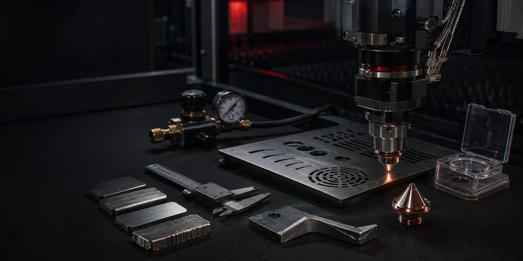
The assist gas clears molten material out of the kerf and controls the chemical reaction. Oxygen can contribute to cutting carbon steel through an exothermic reaction. Nitrogen may be preferred on stainless steel and aluminium when an oxide-free or cleaner edge is the target. Compressed air can be an option that balances operating cost in suitable applications.
Unstable gas pressure, contamination in the line or insufficient purity directly affect surface quality. Regulators, filters and connection points should be checked regularly.
5. Nozzle selection and centring
Nozzle diameter and type determine how the gas flow reaches the cutting zone. A damaged, dirty or unsuitable nozzle can cause asymmetric burr, an irregular kerf and increased gas consumption.
The laser beam must pass through the centre of the nozzle. If centring is off, cuts in one direction may be clean while those in another are problematic. Nozzle height also affects effective gas use and the risk of collision.
6. Cleanliness of optical elements
The protective glass and other optical elements can become contaminated by fumes or spatter. A dirty optical surface degrades beam quality, causes heating and can damage expensive components over time.
Cleaning should be done with the right equipment and method. Optical surfaces should not be touched with bare hands, the inspection intervals specified by the manufacturer should be applied, and damaged protective glass should be replaced without delay.
7. Motion system and mechanical stability
For the cutting head to follow the programmed path accurately, the guides, drive system and machine frame must run stably. Backlash, vibration, loose connections or dirty rails can cause dimensional deviation, especially on small holes and sharp corners.
Acceleration and direction-change control matter as much as high speed. Periodic mechanical maintenance, lubrication and axis checks help preserve cut quality.
8. Programming, nesting and tool path
Where cutting starts, the order of contours, lead-in and lead-out moves and how parts are nested on the sheet all affect the result. Heat building up in one area can deform the sheet, while small parts tipping up can cause a collision with the cutting head.
Techniques such as common-line cutting, micro-joints, bridging and automatic nesting can reduce time and scrap when used correctly. A wrong strategy, on the other hand, can spoil part dimensions or edge quality.
How to proceed when diagnosing a cutting fault
- Determine whether the fault occurs on the whole part, in a particular direction, or only at corners.
- Fix the material and program variables.
- Complete quick checks such as nozzle, protective glass and centring.
- Verify gas pressure and flow stability.
- Test power, speed and focus settings by changing only one variable at a time.
- Record successful parameters together with the material and thickness.
Keep a quality record for consistency
When photographs of sample parts, the parameters used, the material batch and operator notes are recorded, recurring problems can be solved faster. Recording not only good results but also failed attempts helps turn process knowledge into institutional knowledge.
In summary: Laser cutting quality comes from managing material, optics, gas, the mechanical system and programming together. Regular checks and a recorded-parameter approach are far more valuable than one good part: the goal is to sustain the same quality in every shift.